How to Read HVAC Wiring Diagrams Explained
- Nov 7, 2025
- 18 min read
At its core, reading an HVAC wiring diagram is a simple, methodical process. You start at the power source and trace the electrical path through all the safety controls and switches until you reach the final component, or "load."
When you approach it this way, what looks like a complicated schematic suddenly becomes a clear roadmap, letting you see the system's logic in action.
Why Reading Wiring Diagrams Is a Critical Skill
Before you trace a single wire, it helps to understand why this skill is so vital. For any HVAC professional or a really determined DIYer, mastering wiring diagrams is the difference between guessing and diagnosing. It's what separates a quick, precise repair from a frustrating and expensive mistake.
This knowledge directly translates to faster troubleshooting, safer repairs, and more accurate installations. Think of a diagram as the language of the machine. Without it, you’re just staring at a tangled mess of colored wires. With it, you see a logical sequence of operations.
The Real-World Impact of Misinterpretation
Let's be clear: the consequences of misinterpreting a diagram can be severe. A simple mistake, like connecting one wire to the wrong terminal, can instantly fry an expensive control board. That just turned a minor repair into a major replacement.
Beyond the financial hit, there are serious safety hazards. Improper wiring can lead to short circuits, fire risks, or system malfunctions that put a home or business at risk.
For a technician, being able to confidently read a schematic is non-negotiable. It’s the core competency that ensures every repair is done safely, efficiently, and correctly the first time.
The reality is that modern HVAC systems are only getting more complex. With smart controls, variable-speed motors, and advanced sensors all integrated, the simple systems of the past are long gone. The ability to read a schematic isn't just helpful anymore; it's absolutely essential for anyone working in the field today. You'll find many common issues, like when your air conditioner is not working, can be traced back to an electrical fault that a diagram will help you find.
The Industry Standard for Professionals
Proficiency with wiring diagrams is a cornerstone of the HVAC trade. According to industry reports, a staggering 85% of HVAC service calls in North America involve some level of electrical troubleshooting, making diagram interpretation a daily necessity.
The Air Conditioning Contractors of America (ACCA) also found that 78% of HVAC professionals cited misreading diagrams as a leading cause of installation errors. Those errors can increase labor costs by an average of 15% per job. That’s a hit to both the customer’s wallet and the company’s bottom line.
Decoding The Symbols And Language Of Schematics
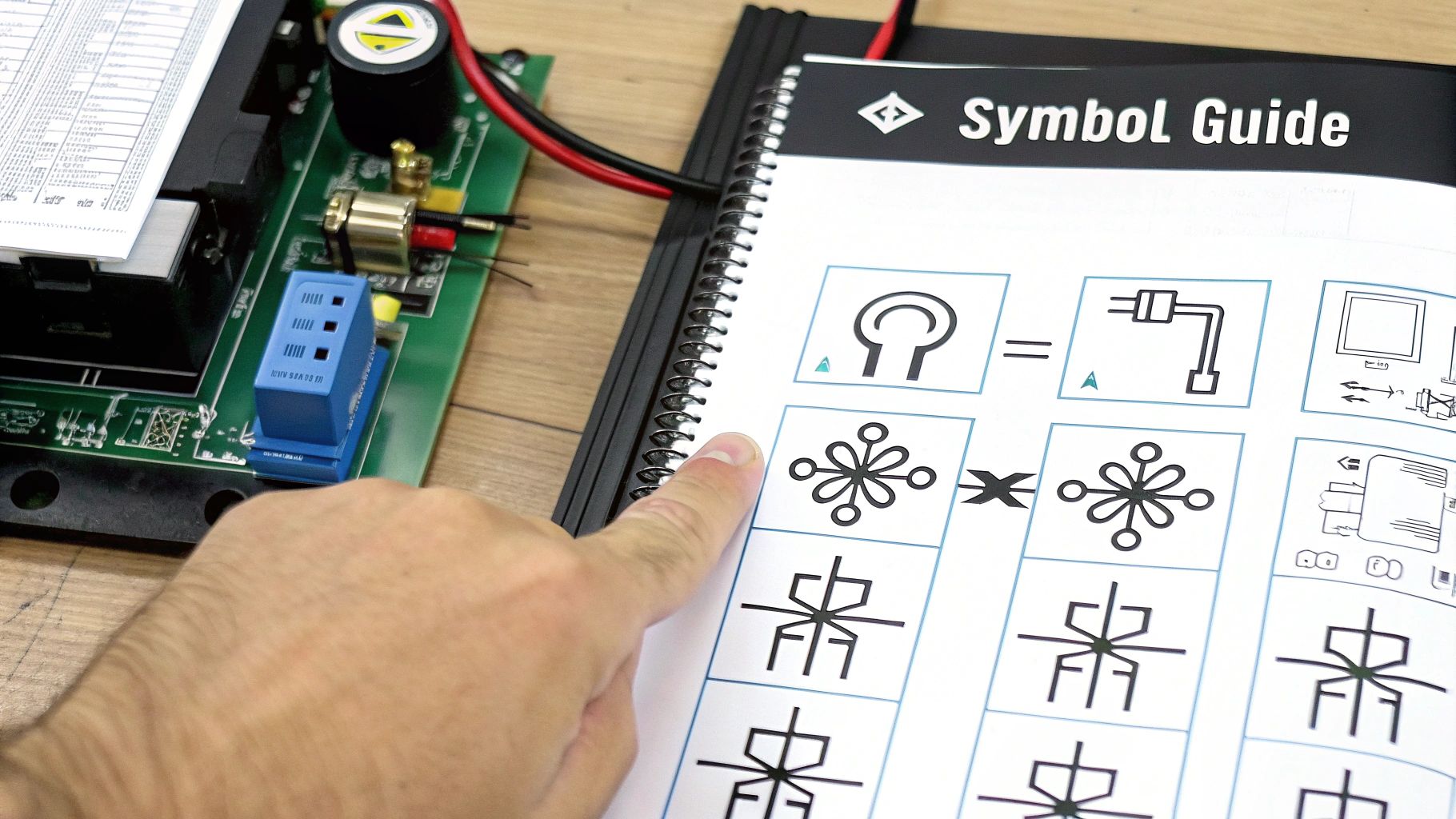
Every HVAC wiring diagram tells a story using its own visual language. Instead of thinking of it as some complex, impenetrable blueprint, try seeing it as a recipe. Each symbol is an ingredient, and every line is a step in the process. To get good at reading these schematics, you first have to become fluent in that language.
Think of this section as your personal translator. We're going to go way beyond just listing symbols and actually dig into what they do inside the system. The end goal here is to transform what looks like a confusing jumble of icons and lines into a clear roadmap of the unit's electrical logic.
Mastering The Core Component Symbols
At first glance, a schematic can be intimidating, just a page full of abstract shapes. The good news is that a small handful of symbols make up the vast majority of any diagram you'll encounter. If you focus on mastering these core components first, you'll build your confidence in no time.
You’ll quickly learn to spot the difference between a transformer and a contactor, or a capacitor and a motor. Each symbol is intentionally designed to give you a visual clue about what that component actually does.
Here's a quick rundown of what you'll see most often:
Transformers: These are usually shown as two coils of wire separated by a few lines. This symbol directly represents their job: stepping voltage down (for example, from 120V line voltage to 24V control voltage).
Motors: Often represented by circles with letters inside (like FM for Fan Motor or CM for Compressor Motor), these are the workhorses that move air and refrigerant through the system.
Capacitors: Look for a symbol with one straight line and one curved line. This represents their role in storing a jolt of electrical energy to help give motors that extra kick they need to start up.
Contactors and Relays: These are just electromagnetic switches, shown as a coil next to a set of contacts. When the coil gets energized, it magnetically closes the contacts to send high-voltage power to a major component like the compressor.
Getting these basic building blocks down is your first major win. Instead of seeing random shapes, you'll start to recognize an organized system where every part has a specific job. For more on making complex visual information easier to digest, some great advice can be found in these step-by-step instructions with pictures for better learning.
The evolution of these diagrams has mirrored the industry's own technological leaps. Back in the early 20th century, schematics were incredibly simple, showing just a few basic parts. As systems grew more complex with programmable thermostats and digital controls, the diagrams had to keep up. The average number of components in a residential schematic ballooned from around 10 in the 1950s to over 50 by the 2000s, making these interpretation skills more critical than ever before.
Common HVAC Wiring Diagram Symbols and Their Functions
To really get comfortable with schematics, it helps to have a quick reference guide. This table breaks down some of the most common symbols you'll see on the job, what they're called, and what role they play in the circuit.
Symbol | Component Name | Function in the Circuit |
|---|---|---|
Transformer | Steps voltage down (e.g., 120V to 24V) to power the control circuit. | |
Motor | The "engine" of the system that drives fans and compressors. | |
Capacitor | Stores and releases an electrical charge to help start motors. | |
Contactor/Relay | An electromagnetic switch that uses a low-voltage signal to control a high-voltage component. | |
Normally Open (NO) Switch | A switch that is open by default and closes when activated (e.g., a thermostat contact). | |
Normally Closed (NC) Switch | A switch that is closed by default and opens when activated (e.g., a high-limit safety switch). | |
Fuse | A safety device that breaks the circuit if the current gets too high. | |
Ground | A safety connection to the earth to prevent electrical shock. |
Keep this table handy as you start looking at real-world diagrams. Before long, you won't even need it; these symbols will become second nature.
Understanding Switches: Normally Open vs. Normally Closed
One of the most fundamental concepts you have to grasp is the state of a switch on a diagram. Switches are the traffic cops of the circuit, controlling the flow of electricity. Their symbols tell you their default position when the system is completely powered off. Getting this right is everything when it comes to troubleshooting.
A Normally Open (NO) switch is drawn with a visible gap in the line. This shows the circuit is broken, and electricity can't flow through it. The circuit only gets completed when something, like a change in temperature or pressure, acts on the switch and forces it to close.
On the other hand, a Normally Closed (NC) switch is drawn with a complete, connected line, showing that the circuit is active by default. Electricity flows through it freely until an action forces it to open, which breaks the circuit. This is extremely common for safety devices, like a high-limit switch in a furnace that stays closed unless the furnace starts to overheat.
Pro Tip: Always, always remember that wiring diagrams show components in their de-energized, or "shelf," state. A normally open switch will be drawn open on the diagram, even if it slams shut the instant the system gets power. This is the baseline you start from for all your diagnostic work.
Cracking The Terminal Code: R, C, G, W, Y
That alphabet soup of terminals on a control board or thermostat isn't random; it's a shorthand for the system's entire sequence of operations. Each letter stands for a specific function, and understanding them is non-negotiable for tracing circuits. While the wire colors technicians use can sometimes be inconsistent, these terminal letters are the universal standard.
Here’s a quick-reference guide to the most common thermostat terminals you'll be dealing with.
Terminal | Standard Wire Color | Function and Purpose |
|---|---|---|
R (or RH/RC) | Red | This is your 24-volt power feed straight from the transformer. You'll see RH for heating and RC for cooling; they are often connected by a small jumper wire in systems that use a single transformer. |
C | Blue or Black | This is the Common wire. It completes the 24-volt circuit by providing a return path for the power that starts at the R terminal. |
G | Green | This terminal controls the indoor fan relay. When the thermostat sends power from R to G, the blower fan kicks on. Simple as that. |
W | White | W is for the heating function. When the thermostat connects R to W, it's telling the furnace or heat pump to call for heat. |
Y | Yellow | Y is for the air conditioning compressor. Connecting R to Y sends the signal to the outdoor unit to start the cooling cycle. |
Getting this terminal logic down is a complete game-changer. For instance, if you have a call where the indoor fan works fine but the AC won't turn on, you immediately know the G circuit is good. The problem has to be somewhere in the Y circuit between the thermostat and the outdoor contactor.
For a deeper dive into these connections, we've put together a complete guide to thermostat wiring color codes. By mastering the symbols, switch states, and terminal logic, you're building a solid foundation that turns a once-confusing schematic into your most powerful diagnostic tool.
Pictorial vs. Ladder Diagrams: When to Use Each
Not all HVAC wiring diagrams are created equal, and they definitely don't serve the same purpose. In the field, you'll constantly run into two main types: pictorial and ladder. Knowing which one to pull out for the job at hand is a huge part of working efficiently.
Trying to trace a circuit on a pictorial diagram is like trying to follow a recipe written into a novel: sure, it’s possible, but it’s the wrong tool for the job. One diagram tells you where a part is, while the other tells you how it works. A seasoned pro knows how to move between both, using them together to get a complete picture of what the system is doing.
Pictorial Diagrams: The Physical Map
Think of a pictorial diagram as a physical map of the HVAC unit. Its main job is to show you the physical location of each component and the general path its wires take. It’s drawn to look like the actual unit, which makes it incredibly useful for one specific task: finding a part.
When you pop open a service panel and need to find the run capacitor or the flame sensor, the pictorial diagram is your best friend. It’ll show you that the capacitor is mounted on the left side of the cabinet next to the contactor, or that the inducer motor is up top.
But its strength is also its biggest weakness, especially for electrical troubleshooting. The wires on a pictorial diagram cross over each other just like they do inside the unit, creating a visual spaghetti mess. This makes it nearly impossible to follow a single electrical path from start to finish. It answers the "where" but doesn't help much with the "why."
Ladder Diagrams: The Logical Blueprint
This is where the ladder diagram, often just called a schematic, saves the day. If the pictorial is the physical map, the ladder diagram is the logical blueprint that shows you how everything is actually wired to work. It completely ignores where the parts are physically located and instead lays out the electrical circuit in a clean, logical sequence.
Ladder diagrams get their name because they look like a ladder:
The two vertical rails represent the power source. This is typically L1 and L2 for high voltage or R and C for the 24-volt control circuit.
The horizontal rungs represent individual circuits. Each rung controls a specific load, like a motor, a solenoid, or a relay coil.
This clean layout makes tracing the flow of electricity incredibly straightforward. You can easily follow a single rung from the power source, through all the switches and safety controls, right to the component it powers. This logical clarity is exactly why schematics are the go-to tool for diagnosing electrical problems.
When a component isn't working, the ladder diagram allows you to methodically test each part of its circuit rung to pinpoint the exact location of the failure. It turns troubleshooting from a guessing game into a systematic process of elimination.
Seeing the Difference in Action
To really make the distinction clear, let's think about a simple circuit for an indoor blower fan.
On a pictorial diagram, you’d see a drawing of the control board, the blower motor itself, and maybe the thermostat. Wires would be shown connecting these parts, often in a jumbled bundle that snakes through the cabinet. You could use it to find the actual fan relay on the board, but you couldn't easily see the sequence of events that energizes it.
On a ladder diagram, that same circuit becomes a single, clean horizontal rung. It would start at the "R" terminal (24V power), run through the thermostat's "G" terminal connection, and end at the fan relay coil. The other side of the coil would then connect back to the "C" (Common) terminal. You can immediately see that for the fan to run, the thermostat must close the connection between R and G, sending power to the relay.
This clarity is what makes learning how to read HVAC wiring diagrams in the ladder format so essential. You need the pictorial to find the parts, but you absolutely need the ladder diagram to understand why those parts are, or are not, doing their job.
A Methodical Approach to Tracing Any Circuit
This is where theory turns into practical skill. Think of a wiring diagram as a roadmap. Like any map, it's most useful when you have a systematic way to read it. I'm going to walk you through a repeatable, methodical process for tracing any circuit, turning a complex schematic into a series of simple, logical steps.
The core principle is simple: start at the power source and follow its path to the component it controls, which we call the "load." Along the way, you'll pass through various switches and safety devices. Understanding this path is the absolute key to effective troubleshooting.
Starting With a Call for Cooling
Let's use one of the most common scenarios as our example: a call for cooling. This whole process kicks off at the thermostat when it signals the air conditioner to turn on. On a ladder diagram, this is your starting point for tracing the low-voltage control circuit.
First, you need to find your power source. On the low-voltage side of things, this is the R terminal. It gets a constant 24 volts from the transformer and acts as the "hot" rail of your ladder diagram.
When the thermostat calls for cooling, it creates an internal connection between the R terminal and the Y terminal. This is the signal. It sends that 24-volt potential out on the yellow wire, headed for the outdoor unit.
But the path is rarely a straight shot. The Y wire's journey almost always includes several safety switches wired in series. This means the electricity has to pass through each one to continue its journey. Common safeties you'll encounter include:
Low-Pressure Switch: This switch is normally closed, letting power pass through. It only opens if the refrigerant pressure drops too low, which protects the compressor from damage.
High-Pressure Switch: Also normally closed, this one opens if refrigerant pressure gets dangerously high, again saving the compressor.
Condensate Overflow Switch: This is a field-installed safety that opens the circuit if the indoor unit's drain pan fills with water, preventing a nasty flood.
The process below really simplifies the mental steps you need to take when looking at any new HVAC diagram.
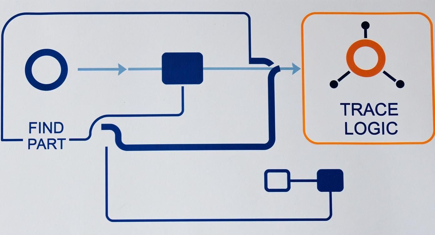
This visual really drives home the two core actions in diagram analysis: first, finding the specific part on the schematic, and second, tracing the electrical logic that actually controls it.
Energizing the Contactor and Triggering the System
If that 24-volt signal successfully makes it through all the safety switches, its final stop is the contactor coil in the outdoor unit. This little electromagnet is the load for our low-voltage circuit.
Once energized, the coil creates a magnetic field that physically pulls a set of high-voltage contacts closed. This action is the crucial link between the low-voltage control world and the high-voltage power world. When those contacts slam shut, they complete the high-voltage circuit, sending power to the compressor and the condenser fan motor. Just like that, your cooling cycle begins.
This methodical approach is fundamental across the entire HVAC industry. According to the U.S. Energy Information Administration, there are over 100 million homes with central air conditioning in the United States, and technicians rely on these diagrams for nearly every single one. In fact, industry data shows the average HVAC tech in the U.S. interprets a wiring diagram at least 10 times per week, which really shows how critical this skill is. You can learn more about the history of this technology from ASHRAE's air conditioning timeline.
Practical Tips for Effective Circuit Tracing
Knowing the path is one thing; physically tracing it on a busy diagram is another. A few simple habits I've picked up over the years can make the process much smoother and less prone to error.
Here's a highly effective, low-tech tip: print the diagram and use a highlighter. As you confirm voltage at each point in the circuit with your multimeter, physically trace that section of the wire on the paper. This gives you a clear visual record of where the power is flowing and, more importantly, where it stops.
When troubleshooting, your goal is to find the break in the chain. By starting at the transformer and testing at each component along the rung (thermostat, safeties, contactor coil), you can systematically isolate the exact point of failure.
This logical process removes all the guesswork. If you have 24 volts going into a pressure switch but nothing coming out, you've found your problem. It's that simple.
Applying the Method to Heating and Fan Circuits
The real power of this methodical approach is that it works for any circuit in the system, not just cooling. The components and wire colors might change, but the fundamental logic stays exactly the same. You always start at the power source and follow the path to the load.
It's a good idea to familiarize yourself with the standard thermostat wiring colors. While there can be exceptions in older or non-standard installations, this guide covers the vast majority of what you'll see in the field.
Standard HVAC Wire Color Code Guide
Terminal Letter | Common Wire Color | Function |
|---|---|---|
R | Red | 24V AC Power from the transformer |
Y | Yellow | Cooling signal to the outdoor unit contactor |
W | White | Heating signal to the furnace or air handler |
G | Green | Fan signal to energize the indoor blower |
C | Blue or Black | Common wire to complete the 24V circuit |
O/B | Orange or Brown | Reversing Valve for heat pump operation |
This table is a great quick-reference, but always remember to confirm with the specific diagram for the unit you're working on.
Example: Tracing a Heating Circuit (Gas Furnace)
Start: The process kicks off when the thermostat connects R (24V power) to W (heat).
Path: That signal travels to the furnace control board.
Sequence: The board then starts its own sequence of operations. It first checks its safety limits (like the high-limit switch), then energizes the furnace inducer motor. We have a great article that explains what a furnace inducer motor does in more detail.
Load: After the pressure switch confirms the inducer is running properly, the board powers the igniter and then opens the gas valve. The main furnace blower is the final load to energize.
Example: Tracing the Fan Circuit
Start: The thermostat connects R (24V power) to G (fan).
Path: This signal travels directly to the furnace control board or a dedicated fan relay.
Load: The relay coil energizes, closing a switch that sends high-voltage power straight to the indoor blower motor.
By applying this same "source-to-load" tracing method to every circuit, you build a complete framework for diagnosing any electrical issue you'll ever encounter. It transforms the intimidating complexity of a full schematic into a series of manageable, individual puzzles you can solve one by one.
Putting Your Skills to the Test in the Real World
Knowing the symbols and how to trace a line on paper is one thing. Applying that knowledge under pressure during a service call, that's where the real skill shines through. This is the moment your ability to read an HVAC wiring diagram stops being an academic exercise and becomes your most valuable diagnostic tool.
Let's walk through a couple of the most common issues you'll face. These examples aren't just about finding the problem; they're about the thought process behind it. The goal is to see how the diagram becomes your roadmap, steering you away from guesswork and toward a precise, logical diagnosis.
Scenario 1: The AC Is Completely Dead
This is probably the most frequent call you'll get. The homeowner says they've set the thermostat to cool, but nothing's happening. No fan, no outdoor unit, just silence. It's tempting to start poking around at random components, but the wiring diagram gives you a much smarter plan of attack.
Grab your multimeter and pull out the ladder diagram. We'll start by tracing the 24-volt control circuit, which is essentially the system's brain.
Start at the Source. Your first check is always the transformer. Are you getting roughly 24V AC between the R (hot) and C (common) terminals? If you don't have power here, the problem is either a dead transformer or an issue with the incoming high voltage. No need to waste time checking anything downstream.
Trace the Call for Cooling. If the transformer is good, the next step is to see if the thermostat is doing its job. Follow the path from the R terminal through the thermostat to the Y terminal. When the thermostat is calling for cool, you should measure 24V between Y and C. If you don't get that reading, your problem is likely a bad thermostat or a broken wire between it and the control board.
Follow the Safety Chain. From the Y terminal, the voltage then flows through a series of safety switches (like low-pressure and high-pressure cutoffs). Test for voltage on both sides of each switch. If you have 24V going in but 0V coming out, you’ve found your culprit: an open switch that's shut the system down.
Check the Final Load. If power makes it through all the safeties, its final stop is the contactor coil in the outdoor unit. A 24V reading across the coil terminals tells you the entire low-voltage circuit is working perfectly. If the contactor still isn't pulling in to start the compressor, the coil itself has failed.
This methodical process, guided by the diagram, lets you pinpoint the exact failure in just a few minutes. To get a better feel for all the components in play here, you can check out this helpful homeowner's guide to the parts of a central air conditioner.
Scenario 2: The Indoor Fan Won't Shut Off
Now for the opposite problem, a component that just won't quit. The customer says the indoor blower runs continuously, even when the thermostat is switched to "Off." This tells you the fan is getting power when it shouldn't be. Once again, the schematic is our guide.
The indoor blower is controlled by the G terminal circuit.
A constantly running fan is almost always caused by one of two things: a stuck fan relay or a short circuit that's sending a constant 24 volts to the G terminal. The wiring diagram helps you figure out which it is.
First, check for voltage between the G and C terminals at the control board.
If you measure no voltage but the fan is still running, the fan relay on the circuit board is physically stuck in the closed position. The board itself has failed and needs to be replaced.
If you do find 24V between G and C, it means the relay is just doing what it's being told to do. The problem isn't the relay; it's a short somewhere in the low-voltage wiring. Most of the time, this happens when the green (G) wire touches the red (R) wire somewhere between the thermostat and the air handler, creating a constant call for the fan.
By using the diagram to guide these simple voltage tests, you can diagnose the problem accurately without any guesswork. And as technology evolves, so do our tools. For instance, new approaches using Augmented reality for maintenance can overlay digital instructions onto the physical equipment, giving techs an interactive guide to complement their diagram-reading skills.
Common Questions About Reading HVAC Wiring Diagrams
Even after you get the basics down, a few questions always seem to pop up when you're staring at an HVAC wiring diagram for the first time. Let's tackle some of the most common points of confusion to really solidify your understanding.
Think of this as a quick debrief before you put your newfound skills to the test on a real unit.
What Is the Difference Between a Wiring Diagram and a Schematic?
This is a big one, and people often use the terms interchangeably, but they serve two very different functions.
A wiring diagram (sometimes called a pictorial diagram) is all about the physical world. It shows you the actual layout of the components and wires exactly as they are inside the unit. Its main job is to help you physically find a specific part you're looking for.
A schematic, on the other hand, is the logical map. Often called a ladder diagram, it completely ignores where the parts are physically located. Instead, it focuses on the flow of electricity and the sequence of operations. Technicians lean heavily on schematics to troubleshoot circuit logic, then use the wiring diagram to find the actual components they need to test.
Where Can I Find the Diagram for My Unit?
Nine times out of ten, the manufacturer has attached the wiring diagram right to the inside of the unit's service panel door. This goes for both your indoor furnace or air handler and the outdoor condenser. You're usually looking for a sticker or a small plastic sleeve holding a folded-up piece of paper.
If it’s gone missing or has been worn down by weather and age, your next move is the internet. Grab the unit's full model number; it’s usually on a data plate on the side of the equipment, and search the manufacturer's website.
What Are the Most Important HVAC Safety Rules?
Safety is everything. Before you even think about taking the cover off a service panel, you absolutely must disconnect all electrical power to the HVAC unit.
Start by flipping the corresponding breaker off in your main electrical panel.
Next, turn off the local disconnect switch. This is usually a separate box mounted on the wall right near the outdoor unit.
Crucially, turning the power off isn't enough. You have to prove it's off. Use a multimeter to confirm there is zero voltage at the unit's terminals. This non-negotiable step is what pros call a "live-dead-live" test.
What Do Dashed Lines Mean on a Diagram?
When you see dashed lines on an HVAC diagram, they typically mean one of two things.
Most of the time, they represent field-installed wiring. This is any wiring that the installing technician had to connect on-site, things like the thermostat wires or connections for optional accessories. This is different from the solid lines, which show factory-installed wiring.
Occasionally, dashed lines might be used to outline a group of components that are all part of a single, factory-assembled part, like an integrated furnace control board. When in doubt, the diagram’s legend should always spell out the specific meaning for that schematic. Tackling these issues is often part of a standard diagnostic process, which is why we've created a DIY guide for when your heater and air conditioner are not working.
At Covenant Aire Solutions, our certified technicians are experts at interpreting complex diagrams to diagnose and fix any HVAC issue correctly the first time. If you're facing a problem you can't solve, trust our team to provide honest, reliable service. Visit us at covenantairesolutions.com to schedule your appointment.